Detecting WMI failure using fuel trims

Turbochargers like high octane and a cold intake charge. Using a water-methanol injection system (WMI) to fulfill that need is effective in terms of results as well as costs (especially if high octane fuel like E85 is not readily available). These injection systems were used in aircraft before World War II and more recently even BMW implemented a system in their M4 GTS. The results speak for themselves – more reliable power!

A Virtual Dyno comparison before and after the WMI system was installed.


The issue with these systems (and any system) is that they can fail, leak, or get clogged. To maintain reliability we need to be able to detect this. There are several ways to go about failure detection. One is to purchase a system with a failsafe while another is to look at temperature differences in the charge air. However some cars (such as the Ecoboost engines) have the charge air temperature sensor BEFORE the injection nozzle (at the intercooler outlet). Unfortunately due to this sensor placement, it will not pick up the difference in temperatures brought on by the WMI spray.

For these vehicles we have another indicator as to whether or not WMI is indeed working. Methanol is combustible. This means that if you inject it, it will affect total fueling entering the engine. The Ecoboost has a sensitive wideband oxygen sensor and it adjusts fueling in real time under wide open throttle (when WMI is also spraying).

This means that you can datalog or monitor your short term fuel trims (STFT) to see if WMI is injecting when it’s supposed to under boost. First you must establish a baseline and check that the system works. Before you turn your WMI system on, take a WOT datalog and make note of your STFTs under boost with WMI off.

stratified-wmi-not-spraying

In the graph above you will see that the STFT settles between positive +5 to +10%. This means the ECU is detecting that it should inject 5-10% extra fuel to meet the fuel targets in the tune. In similar temperatures and without adjusting boost, turn the WMI system on and take another datalog.

stratified-wmi-spraying

You can see that now at the same boost pressure and with WMI injecting the STFT reading has dropped to -5%. This means that WMI is contributing to around 10-15% of the total fueling on this particular car and setup and the ECU is now taking away 5% of the fuel instead of adding 5-10%. Excellent, now you have verified that the WMI system works and have seen its effects on fuel trims. This is your new baseline for fuel trims with the WMI system working.

If the system were to fail, you will see not just additional knock, but also a shift of the STFTs towards positive territory as that extra fuel is no longer supplied.

Keep in mind that engine part changes, WMI nozzle changes, different temperatures, changes in boost pressure, and fueling system changes overall (including the fuel used) will affect the fuel trims in varying degrees. However if you often monitor your car you will have a good idea where the STFT trims sit under WOT with WMI working. If you see a sudden positive shift in those trims accompanied by knock under steady wide open throttle and boost, you should inspect that your water-methanol system is leak free and still delivering the liquid to the engine.

Keeping things fueled and cool,

The Stratified Team

Upgrading the Volkswagen GTI FMIC

I will preface this with the fact that the OEM front mount intercooler (FMIC) on the VW GTI is very good for an OEM unit. Here’s a little comparison between the MK6 GTI and the OEM unit on a MK3 Focus ST. vw-gti-vs-focus-st-intercooler-efficiencyWhen you are looking at the performance of an intercooler you want to look at the difference in temperature between the beginning and end of a wide open throttle run. This change in temperature will tell you whether the FMIC is maintaining a cold air charge or whether it is struggling. The OEM Focus ST FMIC in this case is clearly struggling in comparison to the GTI and this comes down to the size. The GTI/Golf R FMIC is very large by comparison – having the same frontal area as the radiator!

Our COBB Tuned development GTI received its final piece to being fully bolted with the F23T turbo. The Golf R FMIC. The install is quite straightforward. There are a lot of screws to take out of the front end to get to the FMIC (bumper and crash bar must come out) as it is between the AC condenser and radiator so if you DIY this install make sure you keep track of these. Having a second pair of hands and a couple of floor jacks to support the cooling stack as you take out and put in the FMIC helps.

golf-gti-fmic-install

I really do like the design of the cooling stack. Lots of airflow in the front end of this car. The R FMIC has a core that is 5mm thicker and it has 31 rows versus the GTI 27 rows.

golf-gti-fmic-oem-thicknessgolf-r-fmic-thickness

Some data comparisons indicate that on a 4th gear pull the change in temperature from the beginning to the end has dropped from 17.5* F to 9.5* F with the R FMIC. A second advantage to the better flowing and larger R FMIC is a smaller pressure drop across its core. Due to the lower pressure drop and lower temperatures, at the same boost pressure the turbo is more efficient and we also gained around 4-5 g/s of airflow.

vw-golf-r-vs-vw-gti-intercooler-fmic-efficiency

I do recommend this upgrade for stock and upgraded turbos alike. The GTI FMIC is quite good but the R FMIC is a direct fit, relatively inexpensive, and will be worth around 5-10whp and be more resilient during multiple pulls.

Ecoboost Tech: Are throttle closures bad?

A question we get asked a lot in the Ecoboost community is: Are throttle closures at WOT bad? Well, let’s delve a little deeper and see what throttle closures really mean. We’ll first need to dive into a little bit of background knowledge on how the Ecoboost throttle is controlled.Ecoboost throttle and boost datalog

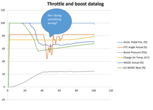
The first important thing to grasp is the concept of Load. Load as defined by Ford is a representation of how much air is filling the cylinder per intake event compared to an ideal amount of air that would fill it at 100*F air temperature and 200*F engine coolant temperature. A load of 1.0 represents that the cylinder has filled with this ideal amount (or in Ford terms “standard”) of air. A load of 2.0 would thus represent twice that amount of air. Another way to think of load is that it represents engine torque output.

By controlling load, we control the amount of air in the cylinder, which directly controls how much fuel we need (for a set AFR), and ultimately the torque the engine produces.

The ECU takes a torque request from the accelerator pedal, applies torque, fueling, and over-temperature limits to it, and ultimately converts that final torque request into a load. These limits can be vital to engine safety and thus the ECU is keen to sticking to its desired loads. This Desired Load is then further converted into a desired air mass.

This air mass then gets worked backwards through a volumetric efficiency model to FINALLY give us a desired manifold absolute pressure (MAP). This pressure can be below atmospheric (vacuum) or above (boost).

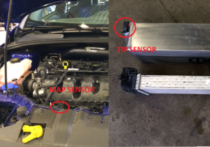
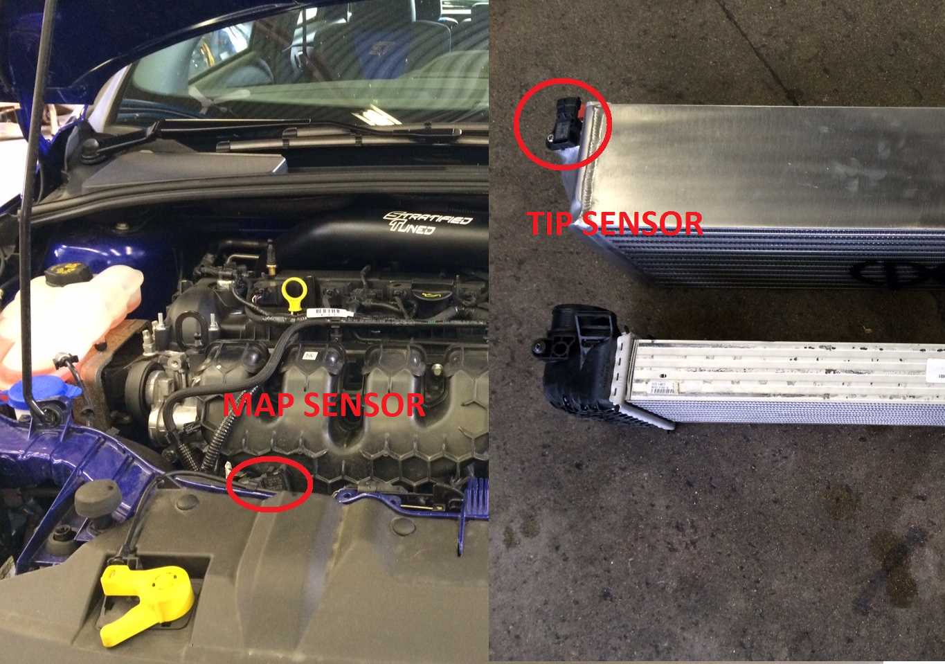
So, we have a desired MAP, but most of us know that Ecoboosts have at least two sensors in the intake tract that measure pressure, one in the manifold (measuring MAP), and one pre-throttle (known as the Throttle Inlet Pressure or TIP sensor).

MAP and TIP Sensor Ford Ecoboost

Theoretically, if the throttle wasn’t a restriction, MAP and TIP should be equal at steady state, but with a throttle in the way, even fully open, there’s a slight pressure drop across the throttle. To solve this issue, Ford actually sets a desired TIP value that is slightly above desired MAP. That way if they try to reach a set TIP pressure, they will simultaneously hit their Desired pressure target.

The throttle plate is opened and closed electronically so that whatever TIP you currently have can be adjusted to your desired MAP. At part throttle, TIP is typically atmospheric since there is no vacuum before the throttle plate, so the throttle remains mostly closed to keep your MAP low. At WOT, you will mainly see a throttle plate that is wide open (about 82% on a COBB AP datalog). The throttle plate moves to make sure we hit our desired pressures and loads/torque as set by the calibration/tune. But wait, there is more!

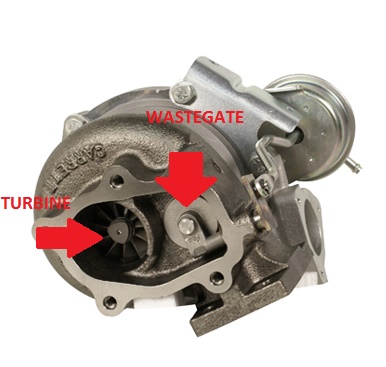
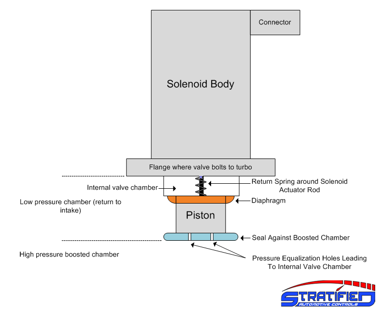
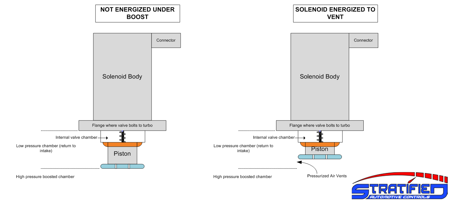
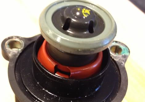
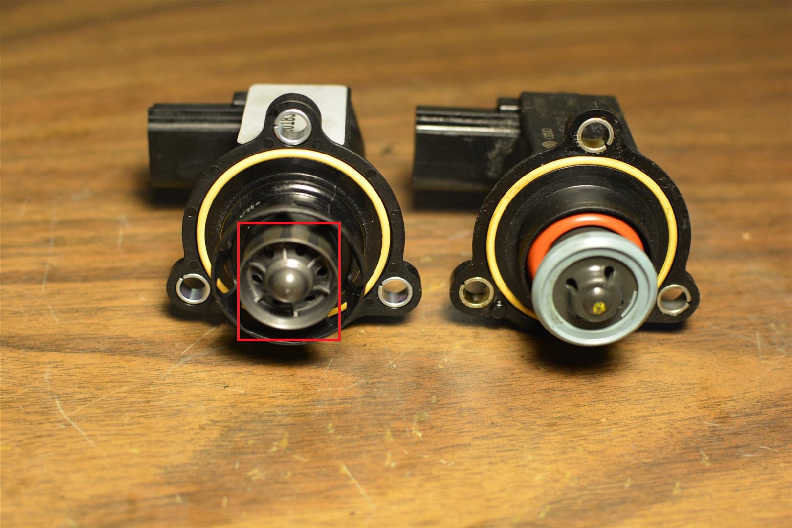
On turbocharged vehicles under high loads the turbocharger is used to pressurize the intake tract to achieve the desired torque we were shooting for. The turbocharger speed and air delivery is controlled by the wastegate, which also receives its inputs from Desired TIP and Desired Airflow. If the throttle is held wide open, it is only up to the wastegate to control how much pressure and airflow we have under boost.

Internal Wastegate

So why then, would we ever want to see a throttle closure at WOT? Typically if you see throttle plate closures under WOT it means your TIP Actual / Airflow Actual ended up higher than what the ECU is asking for. Thus the ECU has to close the throttle to prevent the manifold from getting too much air. As mentioned previously, we may be limiting this for safety, to make sure we have enough fuel, or maybe we even had a component failure (like a wastegate line popping off!) and need the throttle to shut to save us from a costly mistake.

But, that’s not the only case – there is actually a performance benefit to closing the throttle at times and controlling airflow via BOTH the wastegate and throttle. A turbocharger is a mechanical machine that does NOT have instantaneous response. It has an inertia and it takes time to get it to spin up and start compressing air. One of the big things you see discussed is turbo lag or how long it takes to spool. Because we have both the wastegate AND the throttle controlling airflow, we could theoretically pre-spool the turbo a little more than we need at the moment, and use the throttle as a restriction to hold back that extra pressure from the manifold. This has the effect of moving us straight up on a compressor map. We have higher pressure, but the same airflow. The net result is that when we now request the power, we’ve already built up some turbocharger rotational energy and don’t need to spend time building it up! That means a faster response when stepping and requesting that oh-so-sweet turbo induced torque!

Load Control

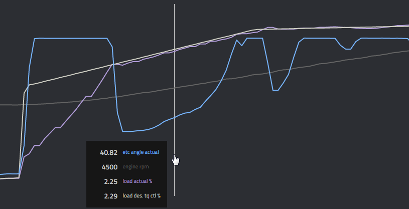
Cut that turbo off! We don’t want more load than we can handle!

This tuning strategy however should not be abused. Keeping the wastegate shut increases pre-turbine pressure, decreases volumetric efficiency, and hurts your fuel economy, so we don’t always want to keep it shut. Like wise, pre-spooling the turbo too much can cause compressor surge. To address this, the ECU controls TIP separate of MAP, which sets a boundary of how much higher we want TIP to be over MAP. As well, the surge line is stored in the ECU and if TIP rises beyond that point, the electronic bypass valve (BPV) can intervene preventing surge. Using this,we can set TIP targets higher in conditions we expect to need acceleration, maximizing performance. This can be a big benefit especially on a road course where you may be part throttle around a sweeper, and once you’re lined up on the straight you can gun it and have a head start on the other cars that take a little longer to spool because they weren’t pre-spooled. However if you see throttle staying consistently at 20-30% for the entire pull, you’re likely dealing with a mechanical or tune issue.

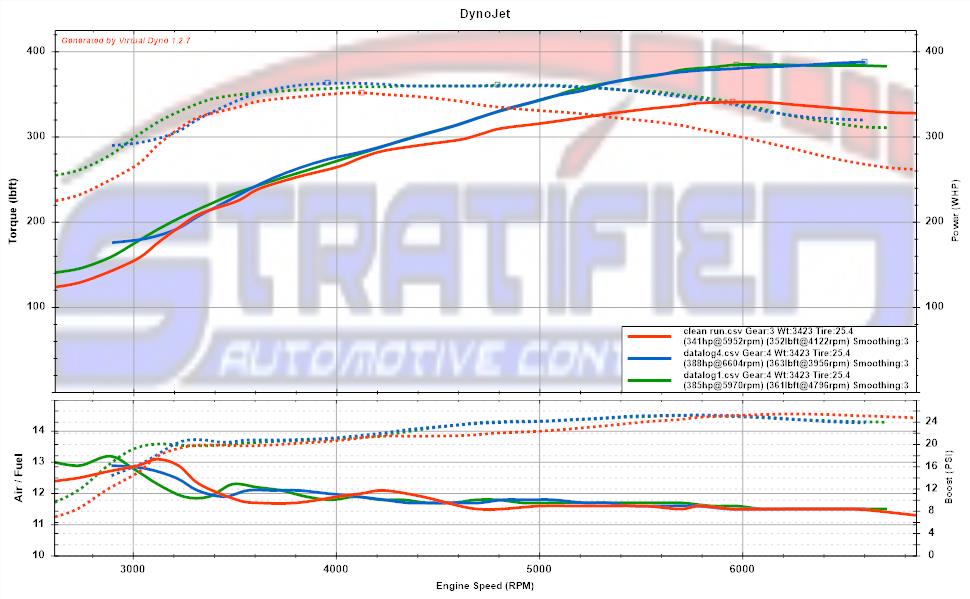
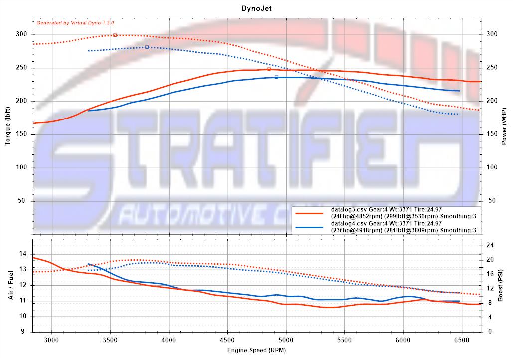
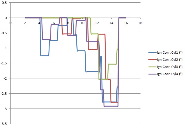
In summary using the throttle smartly when tuning can result in the fastest possible boost response during transient throttle applications while also making sure that boost stays on target. With proper tuning of the system, the wastegate and throttle both allow you to create fast spooling yet smooth and controlled boost. This can be seen on the dyno (or VDyno if you have a clean one without wheelspin!), with nice smooth torque curves lacking any overshoot typical of a poor implementation of mixing throttle and wastegate.

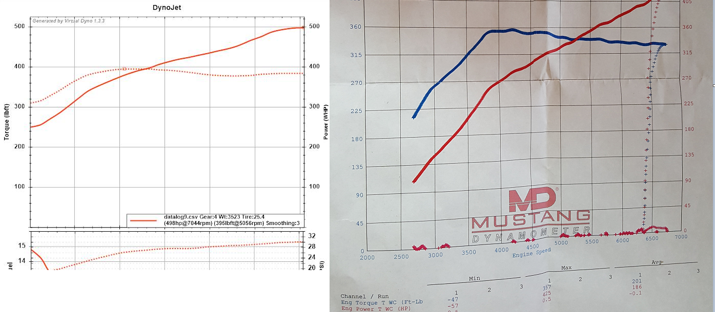
Net result of throttle and wastegate combined: Nice flat torque without overshoot.

So now hopefully it’s clear that having throttle closures isn’t necessarily bad. Quite the opposite – relying on just keeping the throttle open the whole time and using the wastegate only is a step backwards and leaves performance on the table.

VW GTI MK6 Cobb Turboback Installed

Last weekend we had the opportunity to install the COBB turboback exhaust on our Stratified Tuned MK6 GTI. This is a very nice piece of kit and it consists of a full 3″ exhaust from the turbo back replacing the OEM 2.4″ exhaust.

VW GTI exhaust tips COBB Stratified

This short video overviews the constructions of the exhaust and its features:

Now … what about performance? Before getting to the nitty-gritty; where is the performance gained with the turboback? There are two avenues actually.

The first is the drop in post turbine pressure. By replacing the two OEM catalytic converters with a single high flow unit and enlarging the piping diameter from 2.4″ to 3.0″ you are dropping the pressure right after the turbine of the turbo. This in turn increases the pressure DIFFERENTIAL between the exhaust gases before and after the turbo. The end result is that the turbine has more energy input and that in turn means faster spool and more air delivered to the engine via the compressor which is now spun faster throughout the entire rev range.

VW GTI downpipw COBB Stratified

The second area where performance is gained is a drop in pumping losses. The engine must pump exhaust out of its cylinders and that is energy that is wasted. By making the process easier, the engine doesn’t waste as much energy doing this and that translates into more power making its way to the wheels.

After verifying repeatability and ensuring that all other variables are kept consistent (temperature, 91 octane fuel) the downpipe and catback gained +13whp and +18wtq (red line). This is very much in line with our expectations. A catless downpipe will add a little more but at this point it’s the turbocharger that’s the biggest restriction in the exhaust stream. The car previously had a Stratified Tune via the COBB AP, COBB intake and diverter valve replaced with no other modifications
VW MK6 GTI Stg2 91 Dyno StratifiedThe exhaust sound is very much a personal preference … so I will another video do the talking.

What’s next? Time to get more consistent torque delivery with a look at DSG tuning. After this, revisiting E85, intercooling, AND and then moving onto a larger turbo! Stay tuned!


Volkswagen / Audi Diverter Valves: How they work, the limitations, and what you need for your TFSI

VW has been using an electronic diverter valve (DV) on their turbo TSI/FSI engines for a long time. This is a hotly discussed topic in the community as the valves sometimes fail and VW has several revisions of the valve.

As many of you know the purpose of the diverter valve is to vent excess boost when the throttle is closed (you lift off the accelerator or change gear). Without venting this excess pressure, the turbo experiences surge which is actually damaging to the turbo. You can hear this as a fluttering sound.

Due to this it is very important for the DV to function properly. By the same token, when the throttle is open and you are building boost, this valve must stay shut and not vent boost from the high pressure side to the low pressure side. Venting this boost under wide open throttle causes a boost leak and a drop in power.

Let’s start with the basics and outline the components of the valve:

VW Diverter Valve Operation Diagram

The valve in the image above is known as Rev G of the valve and it is found in the earlier Audi and VW cars. Before going any further we have to discuss just how the valve works. All the electronic valves work on the same principle so this applies to all of them.

The light blue piston seal at the bottom of the valve presses against the high pressure side opening inside the compressor housing. This seals the high pressure chamber from the low pressure chamber that connects to the intake right in front of the turbo. This connection between the high and low pressure is all inside the turbo compressor housing and the DV either allows air to pass or not between the two pressure areas.

VW Diverter Valve Operation Explained

The top of the valve houses a solenoid that pulls the piston up when energized opening the valve. The spring helps return the valve to the sealed position and also keeps the valve closed as boost builds up.

Here’s where things get interesting. The spring is much too soft to prevent boost from pushing the valve open. Because of this VW has designed a set of holes at the bottom of the piston shown below. VW Diverter Equalization Holes

These opening allow boost pressure to build insider the internal valve chamber. This chamber is sealed from the low pressure side by the orange diaphragm. This pressure that builds up inside the valve equalizes the forces on the valve and keeps it shut under boost. Once you lift off the throttle, the solenoid pulls the valve open (with a good amount of force and speed) releasing pressure to the intake from both the charge piping as well as the internal valve chamber. The spring then returns the valve to the sealed position.

So how do these valves fail?

VW Diverter Valve Tear

One obvious failure mode is a tear in the orange diaphragm. Once the diaphragm is torn boost will leak from the internal chamber to the low pressure side and the piston itself won’t be held shut as tightly.

VW/Audi have built a more robust valve with the Rev D pictured on the left below. This valve does away with the diaphragm that is prone to failure. There is more to it than just this.

VW Diverter Rev D vs Rev G

Boost leaks and undesirable valve “lifts” happen during transients. That is when you are just building boost, or when you are quickly back on the throttle after a gear shift. During times like these one of two things can happen:

One is that the valve does not return quickly enough to the seated/sealed position. The stiffness of the spring along with the mass of the piston determine this speed. The Rev D valve has a stiffer spring and a faster returning piston.

Secondly, the piston can lift if the internal valve chamber does not fill quickly enough with pressurized air due to the pressure imbalance. You will notice that the Rev D valve has more openings (6 versus 4) than the older valve allowing for faster pressure equalization.

Keep in mind that if the valve does not seal or lifts when it’s not supposed to, you are likely to not just experience low boost, but also a low boost code (P0299). You are also likely to hear a high pitched noise under high boost if you have an aftermarket air intake installed.

VW Diverter Location

If you experience the error code, intermittent boost, or loud whistling, it’s time to check your DV. Upgrading to the Rev D valve can address some of the reliability issues of the older diaphragm based valve. However the Rev D also has potential issues. One is that it doesn’t have a good seal against the compressor housing potentially allowing some boost to leak. Another is that the spring may still be too soft when you are building boost in excess of 25psi quickly.

There are several aftermarket options out there. The key is to have the fastest acting valve with the least amount of surge that still seals. The ECU monitors pre-throttle boost and can also trigger fault codes if the valve is not fast enough or too stiff and there are pressure spikes in the charge piping so keep this in mind. As always, it’s all about building the right solution for your specific needs.

If you have any questions or would like to discuss options and tuning, don’t hesitate to Contact Us.