Subaru WRX LSD Install How To and Tech Talk

lsd-isntall-wrx-2

There was once a time when the WRX came with a rear limited slip differential. Glorious. Unfortunately the VA chassis WRX – at least in North America – comes with no mechanical locking diff. Instead they have a fairly primitive form of torque vectoring which leads to frustrating one tire fires.

As we added power to our development WRX we could either swap in the STI transmission, center and rear diff (which are all mechanically locking) … or … see how much a rear limited slip can help things out.

We went for the latter at a much lower price point and much simpler install and it certainly adds a lot of what was missing from the driving experience. The car is able to put down power (especially in sharp corners and on snow/ice) much more effectively and it is even able to power on oversteer! Yes! Subaru please bring back the LSD as an option for this car – we know Japan has it because that’s the LSD we got.

The unit we installed is a Torsen gear based differential that does not bind at low speeds and uses the OEM 75W90 fluid. The rest of the install we put in video form, so enjoy the the video below and give us a follow for more technical content.

Torque specs below because they are a bit hard to read in the video

torque-specs


Subaru WRX FA20 DIT Tuning – Initial Findings

We have been involved with tuning direct injection turbocharged performance engines for over a decade – so naturally it was time apply our knowledge to one of the most iconic sport compact vehicles on the road today: The Subaru WRX.

subaru-wrx-2018-stratified-2

Initial impressions with the car are that unlike some of its competitors it feels very much like a white canvas. There are no sound symposers, pops, burps or fancy torque vectoring differentials. The full time AWD system adds great traction and the low center of gravity of the drivetrain along with suspension tuning make the car feel very stable. A good sign when you plan on adding power.

subaru-wrx-stratified

Out of the box, it is not impressively fast or punchy. This white canvas feel to the car (a bit of a throwback) is excellent in the sense that it gives the enthusiast a lot to build on an individualize. Our plan is to do just that – build on the character of the car and add enjoyment to the driving experience.

Our first modification (after 160 miles of ownership) was a COBB Accessport. This is the tool of choice for the other platforms we calibrate and it is very well featured on the Subaru platform.

subaru-wrx-cobb-accessport-tuned

We dug right in and built our calibration on the otherwise bone stock 2018 WRX. Below you will see a power comparison between Stock, COBB Stg1 91, and the Stratified tune on the same 91 octane fuel.

subaru-wrx-dyno-stratified-vs-cobb-vs-stock

The interesting thing is that stock (as well as with the COBB tune) the car ran so rich that it actually hesitated under wide open throttle operation. The OEM MAF calibration was around 10% rich using our ethanol free fuel. This is something to keep in mind if your fuel has low ethanol content and if you feel hesitations during acceleration – even stock. Leaning the curve slightly as well as adjusting the MAF and utilizing the wideband O2 under WOT are effective ways we used to address these issues.

You can see that the COBB OTS tune is quite conservative picking up power in the midrange with mild boost increases over stock.

Aside from running a leaner (yet still very much safe) air-fuel ratio which improved driveability and response, we found that even on 91 fuel we were able to add repeatable performance and improve response over the COBB OTS Tune. We did this by increasing boost, adjusting timing, refining boost control, and tuning variable valve timing.

Fuel quality plays a large role in limiting performance beyond this point. We will be working with ethanol shortly as well as adding parts to the vehicle. Stay tuned as we continue the journey with the Subaru DIT and provide custom tuning support for the FA20DIT engine.

The Stratified Team

Focus RS 9000 Mile Checkup

With our RS coming up on 10000 miles and a year of development and (hard) driving, we thought it would be a good idea to borescope the cylinders and see how things look. This is a 2016 September build and the car has definitely been put through its paces on both the track and street.

The good news is that things look great! Spark plugs show the correct heat range (we run a step colder) and even burning across all the plugs.

Digging deeper into each cylinder we see that the pistons have the usual carbon buildup. We also see how effective the bowl design is at directing fuel and preventing it from being projected on the cylinder wall. You can see in the image below that the fuel spray is well contained within the center bowl (and this cleans it of carbon buildup). Keeping fuel off the cylinder walls prevents them from being washed down and oil dilution.

focus-rs-piston-top

Below is a video of one of the bores. The cylinder head gasket is the line in the center of the image. We checked all cylinders and none showed any signs of deterioration at this level. The black staining you see on the piston deck is from carbon deposits and the piston rings not coming up high enough to scrape it off the cylinder wall. This is normal.

Here’s to 10000 more! We will keep you all posted. CheeRS!

Focus RS Head Gasket Failure Mechanism

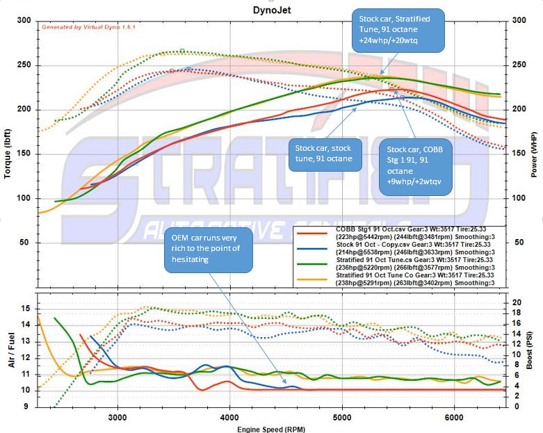
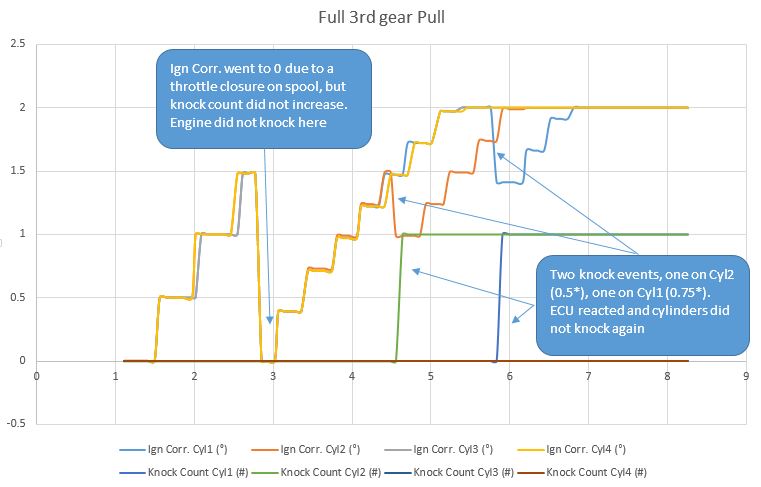
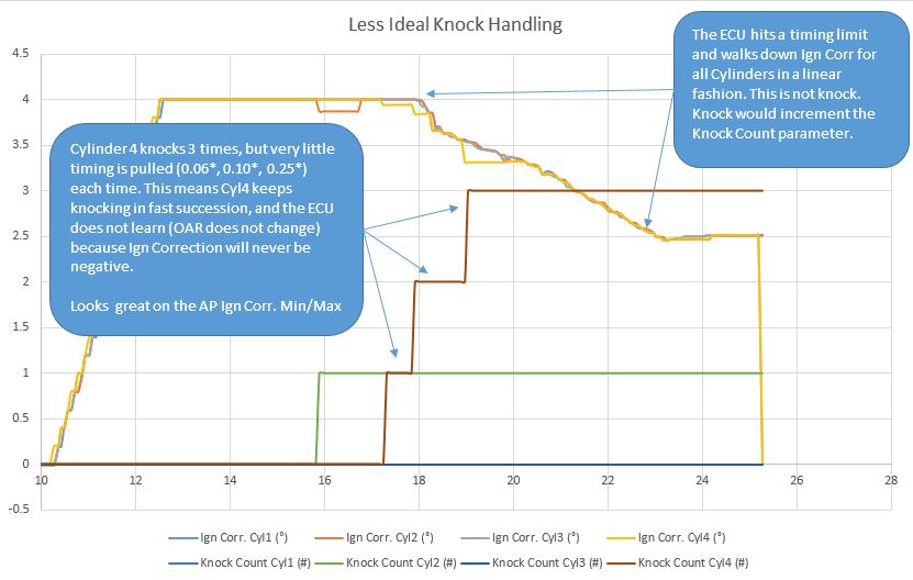
A lot has been made of the Focus RS Ecoboost 2.3 head gasket failures. It seems to be an issue that has occurred in both modified and unmodified vehicles. I am not certain what percentage of vehicles are affected. However we have spent significant time looking at the mechanics of the failure and wanted to share this with our customers and community.

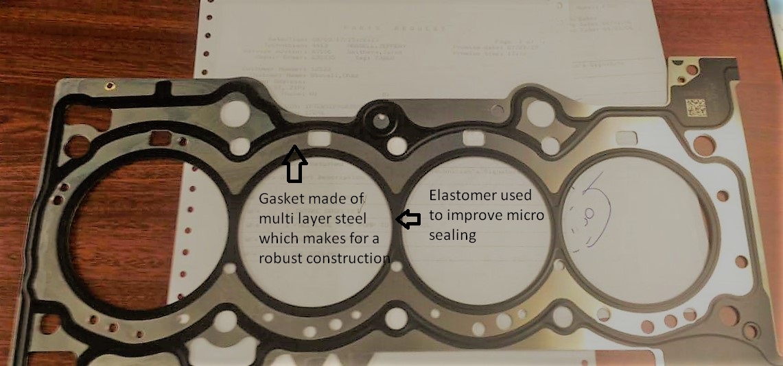
The Focus RS uses a multi layer steel (MLS) head gasket. This is a very capable method for sealing the block to head interface. This multilayer gasket is enhanced by an elastomer that further helps seal critical areas.

mls-head-gasket

The Focus RS 2.3 Ecoboost engine block is an open deck design. This means that the cylinders are not attached to the outside of the block structure at the sealing surface of the head gasket. This space is filled with engine coolant.

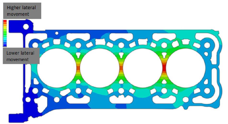
The head and block are secured to each other using torque to yield bolts (which do not require re-torquing the head fasteners after the engine is heat cycled). In spite of this there is inevitable movement between the two sealing surfaces. The two types of movement are vertical movement (which is what causes head lift and a sudden gasket failure) as well as lateral movement. This lateral movement is of most interest in this situation. Minute lateral movement causes what is called gasket fretting/scrubbing. There are two mechanisms that cause this lateral movement:

  1. Thermal deformation. As the engine is brought through a range of temperatures (within normal operation), the expansion and contraction of the head and block cause this lateral movement between the two interfaces. The movement caused by this is however low cycle, as the engine is warmed up and cooled down relatively few times compared to the next mechanism.
  2. The most relevant mechanism for lateral movement is due to cylinder firing. When a cylinder fires, it applies pressure on the open deck cylinder structure. This in turn causes this minute movement between the two interfaces scrubbing them at a high rate.

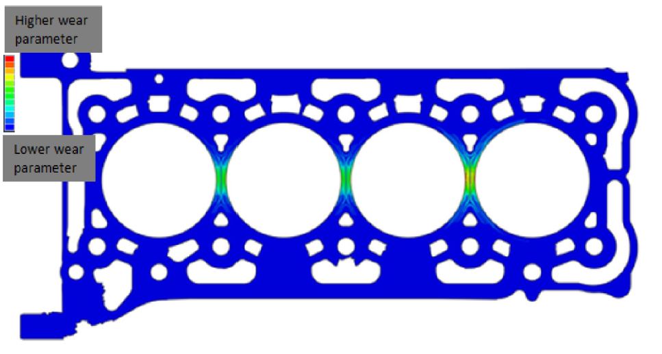
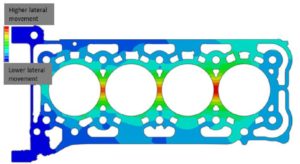
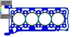
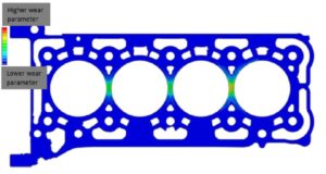
The result of this scrubbing is material loss from the head gasket, block, or head. Over time, the seal between the block and head can fail. The area where it will fail first is the area with: the highest movement, the highest contact pressure, and the least sealing material available.

The area of highest lateral movement for the Focus RS is between the cylinders.

focus-rs-high-head-to-block-movement

The area of highest contact pressure is around the cylinders (because this is where the combustion pressure is highest and needs the best seal). This is by design.

focus-rs-contact-pressure

The area that will inevitably experience the highest wear rate will be between the cylinders. Manufacturing discrepancies, vehicle use, temperature fluctuations and other factors will influence whether a failure will occur on a vehicle and if so when.

focus-rs-high-wear-rate-head-gasket

There are two methods to reduce this scrubbing wear. One is to stiffen the block structure. When rebuilding an engine for example, using the closed deck 2.0 Ecoboost block is an attractive option. However, Ford could not use this block in production and I am certain there are good reasons for this; likely related to emissions certification.

The second method, and what is being implemented as a fix is to redesign the head gasket.

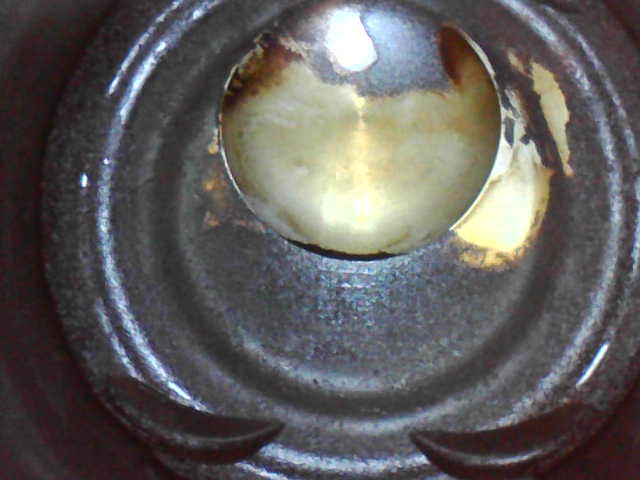
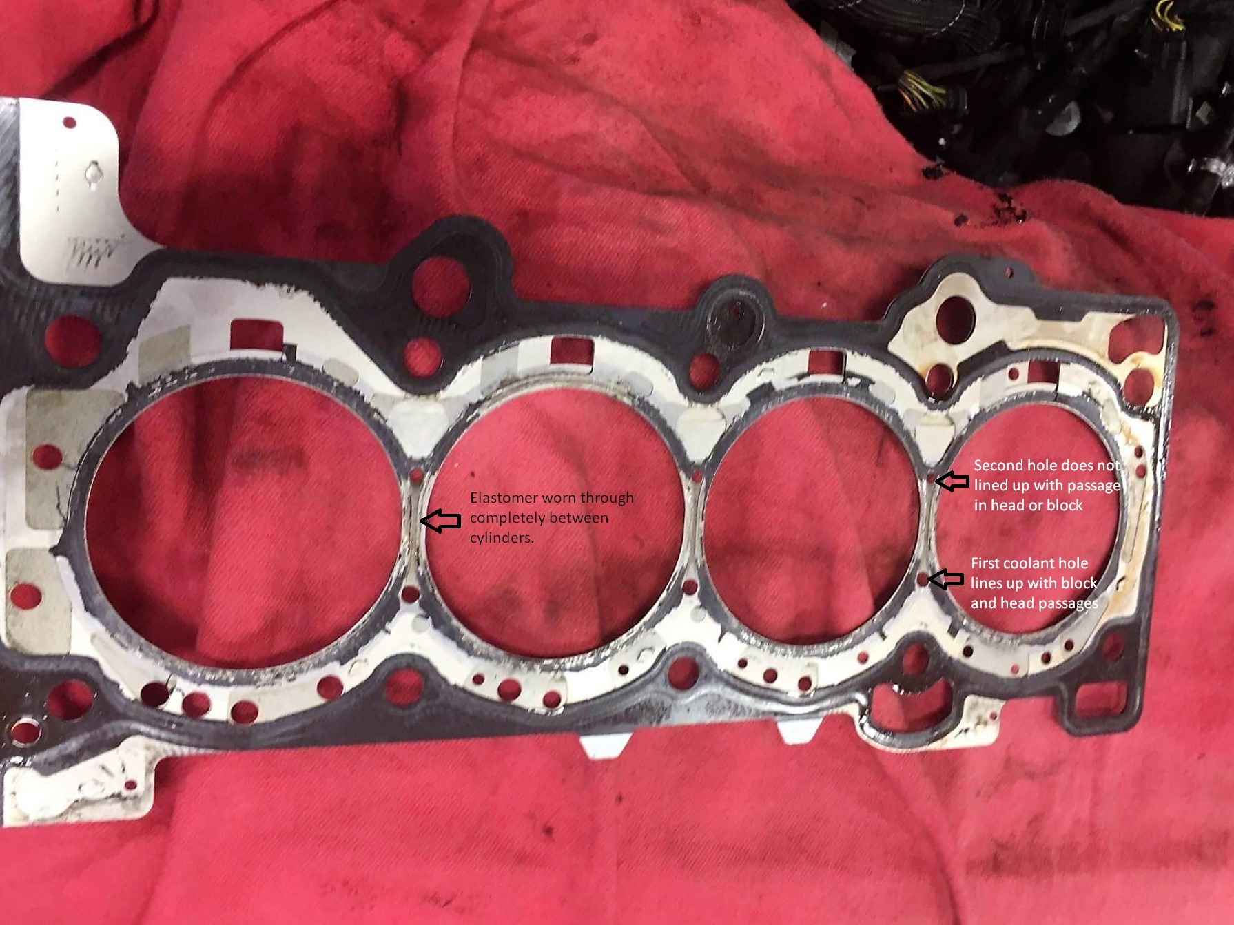
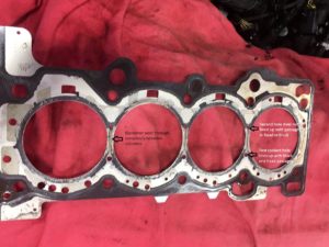
Below is an image of a failed Focus RS gasket. A few things to note:

  • There is a very high wear rate of the elastomer (black section) between the cylinders. This is where the gasket has failed. You can see that it is almost completely missing in these areas.
  • Notice how thin the sealing area is between the cylinder overall.
  • Looking carefully you will notice that the are two holes in gasket between the cylinders marked on the image below.

focus-rs-failed-head-gasket

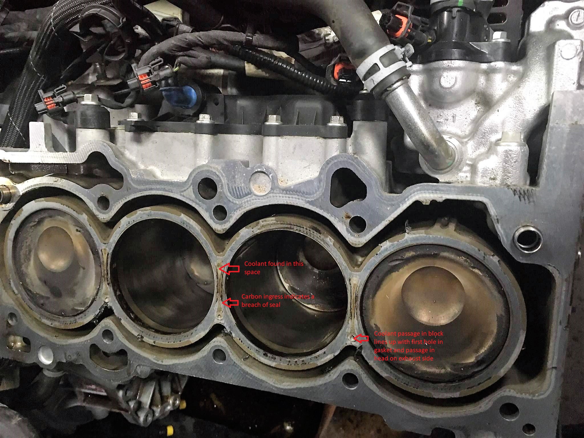
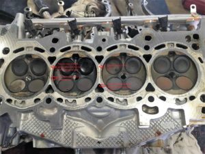
Now let’s have a look at the block. You can see there is a very smallcoolant hole on the exhaust side. This hole lines up with one of the holes in the failed head gasket. You can also see a trail of coolant marking on the block surface leading to the second hole. This shows there is no elastomer between the cylinders on the original head gasket.

focus-rs-block

Looking at the head, you can see that the first hole on the head gasket lines up with a coolant passage. The second hole, however does not line up with any coolant passage. Once again, the head shows that coolant was found in the area between the cylinders but this was a closed path. Overall the cylinder sealing area was very narrow and the head gasket failed after a number of miles.

focus-rs-cylinder-head

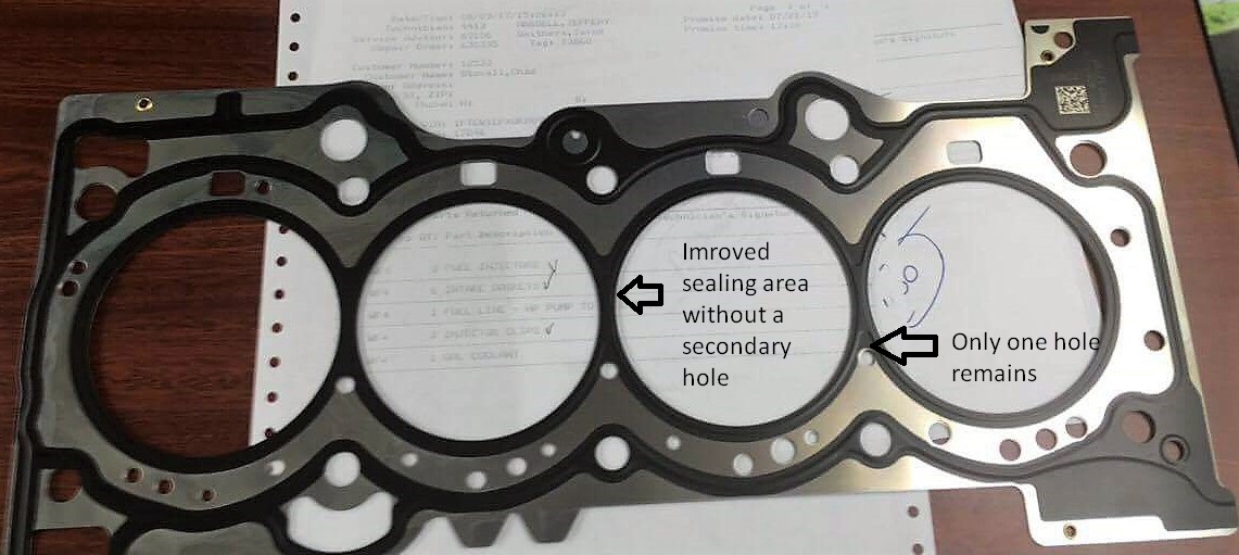
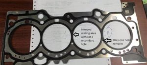
When the car was brought to the dealer, it was repaired with the head gasket shown below. There are some very important changes in the area between the two cylinders on the updated gasket.

  • The second deadheaded hole is no longer present
  • The entire area between the cylinders is now coated in elastomer. This will increase the sealing surface area and better distribute the clamping force in this critical area. This will in turn reduce the fretting/scrubbing failure of the head gasket.

focus-rs-head-gasket

The latest gasket part number is G1FZ-6051-C and this is what dealers are replacing failed gaskets with on vehicles that experience this failure. I am not sure at what point the factory engines have received this latest gasket part number. The only indication I was given was that this part number was available to service centers sometime between 3/27/17 and 8/10/17. Again, this says nothing regarding when this change was made to vehicles coming out of the factory.

I hope this clears up some of the confusion around these head gasket failures and what is causing them. The symptoms of failure are:

  • Loss of coolant.
  • Misfires, especially on a cold start and rough running.
  • Coolant fouled/wet spark plugs.

If you experience these symptoms, take the car in to Ford for the fix. Otherwise, enjoy the RS! It is not the only car in history to experience difficulties with head to block sealing. High output, low emissions, small displacement engines like the RS are a challenge to engineer and can have some teething issues; but at the same time we can all agree that fun behind the wheel was certainly well engineered!

The Stratified Team

Photo credit:

Brewer, T. and Chen, X., “Cylinder Head Gasket Fretting/Scrub Mechanism Investigation and Analysis Procedure
Developments,” SAE Technical Paper 2017-01-1091, 2017, doi:10.4271/2017-01-1091.

How the Knock Detection System Works in the Ecoboost

The Ford Ecoboost knock detection system is one of the more complex systems out there. A lot of the vehicles using the Ecoboost engine are rated to use fuel that ranges in octane from 87 to 93 octane. Because of this, Ford built a system that is very powerful and adaptive. It actually learns your fuel quality while you drive. All the EB engines we work with use this adaptive timing system. This is great for us calibrators as we can build failsafes and adaptability into the tunes – but it has to be setup correctly.

The knock detection system starts with the sensors (microphones) that pick up engine noise and are mounted to the engine block. If the engine noise falls within the correct frequency and window of operation (around the time the spark plug fires), the ECU registers this as knock. When knock is registered, the ECU looks at the Knock Response table pictured below. Based on the intensity of the knock it subtracts timing advance from the Ign. Corr. Cyl X Parameter (which you can view and datalog) on a per cylinder basis. On each knock events it also increments the Knock Count Cyl X parameter which can also be viewed. Both of these parameters are reset to 0 once you let off the throttle, shift gears, or experience a throttle closure.

Keep in mind that the following ECU tables shown have OEM values. We adjust these to better suit our performance criteria, but the principles remain the same.

ignition-reduction-table

The amount of timing being pulled for each knock intensity and engine speed is completely under the control of the tuner who builds the tune. You want to make sure that you pull enough timing per knock event to maintain engine safety and stop the knocking. Here’s how this looks in a graphed datalog of a single cylinder during a pull.

ecoboost-knock-count-and-ignition-correction

These negative ignition values are always subtracted from the current Ign Corr. Cyl X variable for each cylinder. This is important to understand because the Ign Corr. Cyl X variable also ADDS timing when the system does not “hear” any knock and you are on the throttle.

The rate at which timing is added and how much total timing is being added is also adjustable in the tune. Ideally the tune should walk timing up at a reasonable rate that is not so fast such that knock is induced and not too slow such that performance is left on the table.

One thing that has to be understood is that all engines will knock at some point regardless of tune and fuel used. The combustion process is a chaotic process and sometimes you get some irregularities. This is inevitable. You want to tune out heavy and sustained knocking, but completely eliminating all knock is not something that is realistic – especially in a street engine. Handling knock correctly is the key. Light knock will NOT damage an engine especially if timing is reduced via a reduction in Ignition Corrections when it happens. LSPI (Super Knock) and bouncing off a Rev Limiter have a MUCH more damaging effect on the pistons and rods.

The beauty behind this knock control system that both adds and subtracts timing is that it also LEARNS the quality of your fuel over time. The learning variable is called OAR (Octane Adjust Ratio). This variable is like a fuel trim but used for ignition and load/boost targets. It can range from -1 to 1. Below is the table that allows the ECU to learn and adjust OAR. You can see from this table that in order for this system to work, ignition timing and the Knock Response table must be set such that the ECU can ADD and SUBTRACT enough timing to make the Ign. Corr. Cyl X parameters positive as well as negative during a pull. With an adaptable tune you are likely to see Ign. Correction numbers that are both positive and negative at times.

how-oar-learning-works-ecoboost

Finally, this OAR number is not just another pretty face. It affects the timing AND load/boost tables the car will be targeting. An OAR that is closer to 1 will remove both timing and boost reducing future knocking. An OAR closer to -1 will add timing and boost due to good quality fuel and increase performance. It is normal for OAR to fluctuate slightly depending on your fuel quality and driving conditions (5th gear pulls are more likely to knock compared to 3rd gear pulls and OAR will adjust to reflect this). Below is the timing table that is multiplied by OAR in the OEM calibration and added to the overall ignition timing the ECU runs. In this case an OAR of -1 will add 4* timing and an OAR of 1 will remove 4* of timing near redline. OAR dependent boost/load limits are setup via a blend of several tables not shown here.

oar-multiplication-table-ford-ecoboost

It should be clear now that NEVER seeing any negative corrections is an indication of a tune not setup to use this learning system to its full potential. This is not ideal on a street driven car as it means that it will not adapt to keep the engine safe when fuel quality or driving conditions change nor will it extract more performance when the situation allows. 

Keep in mind that these knock detection systems are extremely fast to react. If knock is detected, if setup correctly, the system will very quickly pull timing to stop the knocking during that pull and adjust the tune for future pulls. Excessive repeatable knock or only positive ignition corrections are something that should be addressed in the tune – and can only be done by the person that has set the tune up. More on knock in this article. 

Now let’s have a look at a set of logs see this in action across four cylinders.

Here’s a normal 3rd gear pull with all 4 cylinder Ign Corrections and Knock Counts graphed. As you can see, ignition timing walks up when there is no knock in a step-wise fashion. When there is knock it drops down stopping further knock. If the knock events happened earlier in the pull or were of a higher intensity, Ign Correction could have become negative.

ecoboost-knock-count-and-ignition-correction-2

Here is how we can setup the same knock detection system in a less ideal manner. At first glance, it looks like this engine is basically not knocking at all. However if you look carefully, you can see that there were 4 knock events. The amount of timing pulled for each event is very little. This does two things. One, not enough timing is being pulled to stop the occurrence of further knock. Secondly, pulling so little timing will mean Ign Correction values will not be negative even though the engine could be knocking heavily and continuously. This in turn will mean the OAR will not adjust and the tune will not adapt to the fuel quality used.

ecoboost-poor-knock-handling

For this reason, watching Min/Max Ign Correction on the AP can be very misleading. Not only does it not show you how many times the engine knocked, it also doesn’t show you how intense the knock was. To determine the performance of the tune, a full datalog is always necessary or at least a good understanding of HOW the tune handles knock events. 

Happy Tuning,

The Stratified Team